Sisällysluettelo
- The Safety Core of Every Battery Pack
- What Is a PCM Protection Board?
- What Is a BMS?
- PCM vs BMS: Key Differences
- How Protection Thresholds Are Chosen
- PCM, Connectors and Pack Accessories
- FAQ
- Do I need a BMS if I have a PCM?
- Can a protection board revive a damaged cell?
- What happens when the protection trips?
The Safety Core of Every Battery Pack
A lithium battery pack is more than a group of cells wired together. Its dependable operation depends on a protection circuit that watches the cells and disconnects the load or charger when conditions leave a safe window. In pack design discussions, two terms appear repeatedly: PCM (protection circuit module, or protection board) and BMS (battery management system). They are related, but they are not interchangeable, and choosing the wrong level of protection for an application can lead to either an over-designed, expensive pack or an unreliable one.
This guide explains what a PCM does, what a BMS adds, how they differ, and how protection thresholds are selected for custom packs. It follows our series/parallel and PCM design guide and complements the broader OEM pack guide.
What Is a PCM Protection Board?
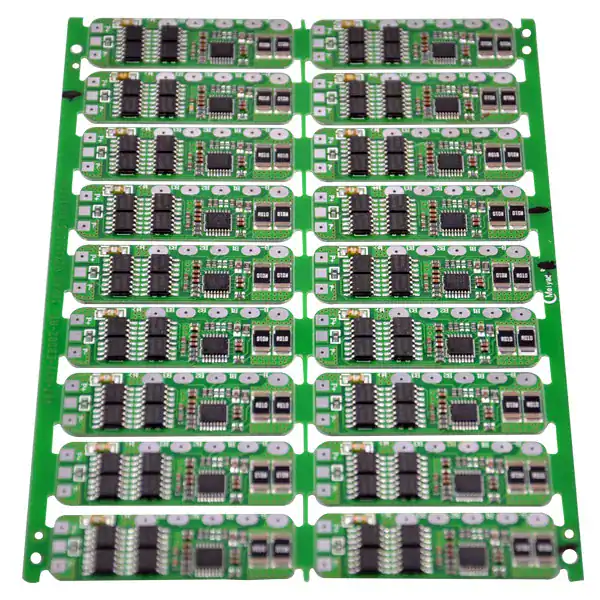
A PCM (protection circuit module) is an electronic board built around a protection IC and MOSFET switches that monitor the pack and disconnect the power path when a fault is detected. In a typical Li-ion or LiFePO4 pack, the PCM guards against the most common failure conditions: ylilataus, ylipurkaus, excessive discharge current and short circuit. Many PCMs also include a temperature sensor that cuts the path if cells or the board overheat.
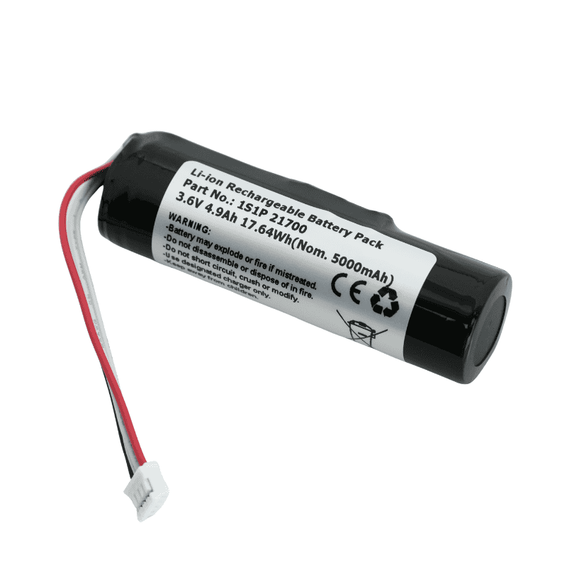
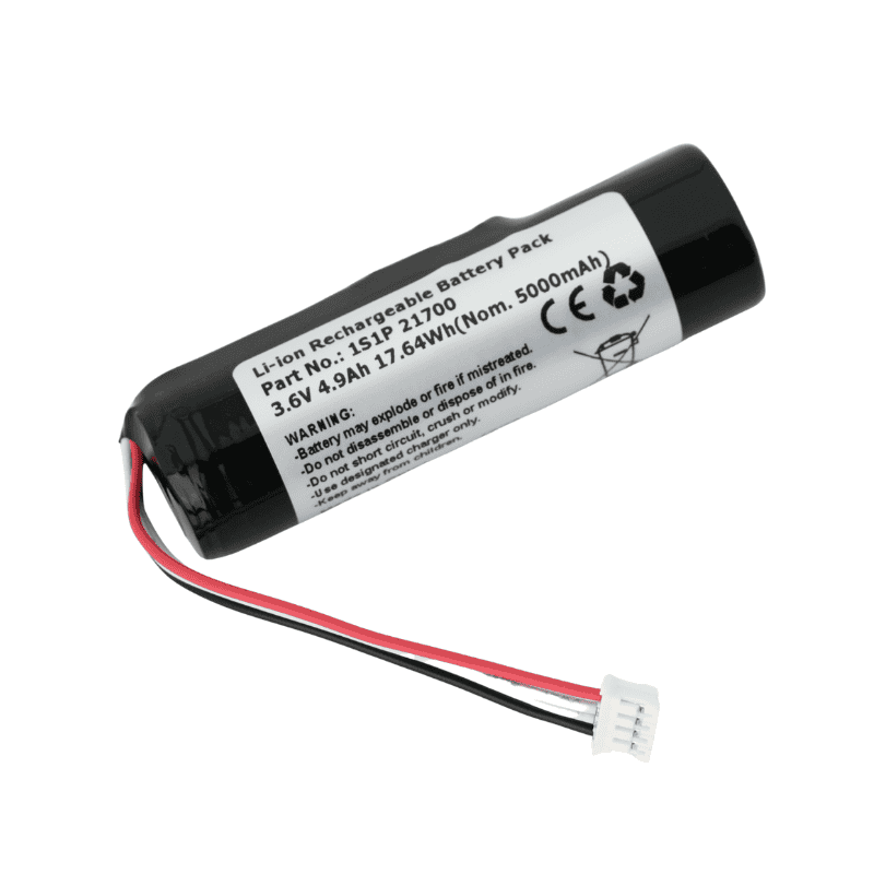
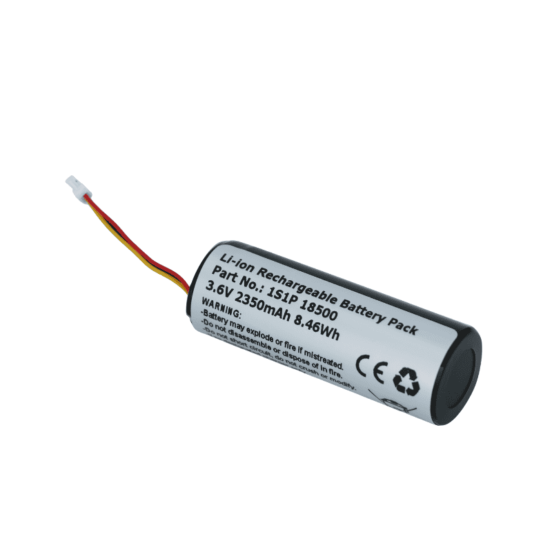
For single- and small-series packs, the PCM is often the complete protection solution. It is relatively compact and low cost, and it is integrated directly into the pack alongside the cells and wiring. Keeppower stocks and supplies PCM-suojalevyt for common series configurations, kuten 4S-1548 protection board for four-series Li-ion packs. When paired with protected cells, the PCM forms the first line of defense against abuse and fault conditions.

What Is a BMS?
A BMS (battery management system) extends beyond basic fault protection. In addition to overcharge, ylipurkaus, over-current and short-circuit monitoring, a BMS typically handles cell balancing, lataustilan arvio, state-of-health reporting, communication with chargers or host systems, and often thermal management control. It is used in higher-voltage, higher-capacity or safety-critical packs where individual cell behavior must be tracked and managed continuously.
Where a PCM primarily reacts to faults by opening the power path, a BMS actively manages the battery during normal operation: it redistributes charge between cells to reduce imbalance, reports capacity and health data, and can coordinate charging and discharge strategies. BMS solutions are common in larger battery packs for energy storage, ajoneuvoja, robots and industrial equipment where reliable data and balanced cycling matter.
PCM vs BMS: Key Differences
| Function | PCM Protection Board | BMS |
|---|---|---|
| Ylilataussuoja | Kyllä | Kyllä |
| Ylipurkaussuoja | Kyllä | Kyllä |
| Ylivirta / oikosulku | Kyllä | Kyllä |
| Lämpötilan seuranta | Often included | Kyllä, with control logic |
| Solujen tasapainotus | Yleensä ei | Kyllä |
| lataustila / health reporting | Ei | Kyllä |
| Communication with host/charger | Ei | Often yes |
| Typical pack size | Single and small-series packs | High-voltage, high-capacity packs |
The distinction matters during specification. A small consumer or device pack rarely needs the cost and complexity of a full BMS; a well-matched PCM is sufficient. Larger multi-cell systems, toisaalta, benefit from balancing and monitoring that a basic PCM cannot provide.

How Protection Thresholds Are Chosen
Protection boards are only useful if their cut-off thresholds are set correctly. The overcharge threshold must stay below the maximum cell voltage the chemistry tolerates, the over-discharge threshold above the voltage at which cell damage begins, and the current cutoffs above the pack’s normal continuous and peak demand but below a dangerous level. These thresholds are derived from the cell manufacturer’s specifications and the device’s operating limits.
Series count also shapes the choice. A two-cell, four-cell or six-cell pack each needs a protection board matched to its series configuration, and the balance leads must connect to each cell group. Keeppower’s pack builds pair the selected cells with an appropriate PCM tai, where required, a fuller BMS, and the finished pack undergoes load and protection testing before release. The series/parallel PCM guide walks through how pack voltage and capacity are calculated alongside protection selection.
It is worth separating protection from performance. A protection circuit cannot make a weak cell deliver more current, and it cannot compensate for undersized wiring or a connector that overheats. Its job is to hold the pack inside a safe operating envelope: cutting charge before the cell reaches its upper voltage limit, cutting discharge before it drops too low, opening the path on excessive current or a short circuit, and signaling a fault through temperature sensing when heat becomes a risk. Designers should review these functions alongside the cell choice rather than treating the protection board as a generic add-on that works with any pack.
Another common point of confusion is balancing. A basic PCM protects the pack but does not actively redistribute charge between cells; over many cycles, series cells can drift apart in state of charge, which reduces usable capacity and stresses the weakest cell. A BMS addresses this through active or passive balancing and by reporting state of charge and health, which is why larger packs and safety-critical systems tend to move up to a BMS even when a PCM would technically prevent a catastrophic fault.

PCM, Connectors and Pack Accessories
The protection circuit does not operate in isolation. The power connectors must carry the pack’s maximum current without overheating, the wiring gauge must keep voltage drop low, and the cell holders, spacers and enclosure must keep the pack mechanically stable. Keeppower supplies the full accessory ecosystem used in custom packs: liittimet, akkukotelot, spacers and holders, USB-sovittimet ja USB-kaapelit. The connector comparison guide explains how XT and JST formats are matched to pack current.
For any custom pack, the protection design should be reviewed alongside the cell choice and mechanical layout rather than added at the end. If you are planning an OEM battery project, define your voltage, kapasiteetti, peak current and environmental requirements early so the PCM or BMS can be specified correctly. You can discuss the project through the yhteydenottosivu.
FAQ
Do I need a BMS if I have a PCM?
Ei välttämättä. A PCM handles the essential fault protection for many single and small-series packs. A BMS becomes worthwhile when you need cell balancing, state-of-charge or health reporting, or communication with a charger or host system. The choice depends on pack size, jännite, capacity and safety requirements rather than on a fixed rule.
Can a protection board revive a damaged cell?
Ei. A PCM or BMS protects the pack by disconnecting the power path, but it cannot repair a cell that has been damaged by deep discharge, ylikuumeneminen, physical abuse or manufacturing defect. Damaged or swollen cells should be removed and replaced, and the cause of the fault should be investigated before the pack returns to service.
What happens when the protection trips?
When a fault threshold is reached, the protection MOSFETs open and cut off either charging, discharging or both, depending on the fault. The pack typically recovers once the fault condition is removed—for example, when the charger is disconnected or the load is removed. If the protection trips repeatedly, inspect the cells, johdotus, connector and charger for underlying problems rather than repeatedly resetting the pack.