Sisällysluettelo
- What Is a Prismatic Battery Pack?
- When Prismatic Cells Make Sense
- Cell Matching and Pack Architecture
- Hitsaus, Busbars and Interconnects
- Suojaus, BMS and Electrical Integration
- Enclosure, Sealing and Mechanical Build
- Validation Testing Before Release
- FAQ
- What is the difference between prismatic and pouch cells?
- Are prismatic packs safer than cylindrical packs?
- How long does a custom pack prototype take?
What Is a Prismatic Battery Pack?
A prismatic battery pack uses rectangular prismatic cells—rigid, flat cells held in a hard case—arranged into a multi-cell assembly with protection, interconnects and an enclosure. Prismatic formats are common where space must be used efficiently, because the flat cells pack together with little wasted volume, and they can be built into slim or rectangular battery compartments alongside electronics. Understanding how a prismatic pack is designed and built helps OEM buyers compare suppliers and specify a pack that fits their mechanical and electrical requirements.
This guide walks through the stages of custom prismatic pack development: cell selection and matching, series and parallel architecture, welding and interconnects, protection integration, enclosure design and validation testing. It complements the OEM custom pack guide and our overview of räätälöityjä akkupaketteja.

When Prismatic Cells Make Sense
Prismatic cells are chosen when the pack shape must fit a defined compartment, when flat, layered construction is advantageous, or when the product needs a rigid battery block that resists internal movement. They differ from pouch cells, which are flexible soft packs, and from cylindrical cells, which are round and held in holders or spacers. The right format depends on the enclosure geometry, weight target, discharge profile and safety requirements rather than on a single preferred cell type.
As with any pack, the starting point is the application’s electrical and mechanical brief: target voltage, kapasiteetti, huippuvirta, käyttölämpötila, dimensions and connector type. Keeppower evaluates each project to select the most suitable cell format—prismatic, cylindrical or pouch—and builds the pack around that choice. For chemistry background, katso Li-ion vs LiPo vs LiFePO4 comparison.
Cell Matching and Pack Architecture
Before assembly, cells are matched for capacity, voltage and internal resistance. Unmatched cells create imbalance: some cells work harder than others, heat unevenly, and fade faster. Matching protects both cycle life and safety in a multi-cell pack. Once matched, cells are arranged in series to reach the required nominal voltage and in parallel where additional capacity or current sharing is needed; the S and P counts follow from the motor, controller or electronics specification.
The pack architecture also determines where the protection board, balance leads and connectors sit. Series strings must be balanced, and the layout should keep high-current paths short and direct to minimize resistance and heat. Meidän series/parallel and PCM design guide explains how voltage and capacity are calculated during this stage, samalla kun PCM vs BMS article covers the protection options available.
Hitsaus, Busbars and Interconnects
The physical connections between cells carry the full pack current, so their design and build quality are critical. Nickel tabs or busbars are joined to cell terminals by resistance or ultrasonic welding, producing a joint with low resistance and sufficient mechanical strength. Poorly welded or loosely connected tabs are a common source of heating, voltage drop and field failure, so weld quality is inspected as part of the assembly process.
Interconnects are routed to avoid stress on cell terminals, and insulation is applied where tabs or busbars could contact the enclosure or each other. In packs that require serviceability, connectors and leads are designed so the pack can be opened safely for inspection. Supporting components such as cell spacers and holders ja akkukotelot are selected to keep the cell block stable and isolated.

Suojaus, BMS and Electrical Integration
Every prismatic pack needs a protection circuit matched to its chemistry and series count. A PCM handles overcharge, ylipurkaus, ylivirta- ja oikosulkusuojaus, while larger or safety-critical packs may use a fuller BMS that adds cell balancing and state-of-health reporting. The protection thresholds are set below the cell’s safe voltage and current limits, and the board is integrated with the pack’s balance leads and power output.
Electrical integration also covers the output connector, balance lead and any temperature sensing wired back to the protection or host system. Connectors are chosen for the pack’s continuous current and polarized to prevent reverse connection; the connectors range ja connector comparison guide outline the common XT and JST formats used in packs.

Enclosure, Sealing and Mechanical Build
The enclosure protects the cell block from impact, tärinää, dust and moisture, and it holds the pack’s shape under load. Wall thickness, material choice and internal fixation are designed around the product’s environment—whether the pack sits inside a consumer device, a piece of outdoor equipment or a marine system. Cable exits and connectors are sealed where water or dust exposure is a risk, and strain relief protects the harness from pulling on solder joints or crimps.
Thermal considerations are built into the mechanical layout as well. Cells need room to dissipate heat, and the enclosure should avoid trapping heat around the protection board and interconnects. For cold-environment products, low-temperature cell options may be specified; the cold-weather guide details the voltage and capacity trade-offs involved.
Validation Testing Before Release
A custom pack should be validated before it reaches the customer. Basic validation includes capacity and runtime verification, charge and discharge cycle checks, internal resistance measurement, and confirmation that the protection board trips correctly under over-current, overcharge and over-discharge conditions. Mechanical checks cover welds, connections, enclosure fit and cable strain relief, and packs shipped internationally should meet UN38.3 transport requirements with the accompanying test documentation.
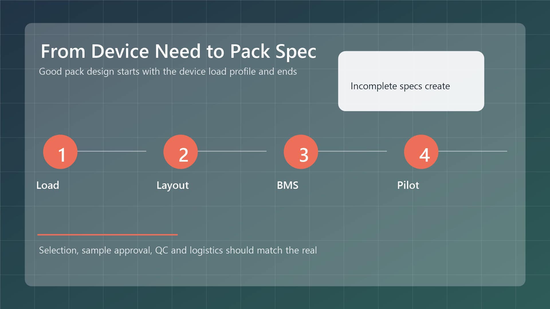
| Stage | Key Activity | Outcome |
|---|---|---|
| Erittely | Define voltage, kapasiteetti, nykyinen, environment and connectors | Cell format and architecture chosen |
| Kokoonpano | Match cells, build S/P arrangement, weld interconnects | Mechanically sound cell block |
| Electrical | Integrate PCM/BMS, balance leads and output connector | Suojattu, functional pack |
| Enclosure | House, seal and strain-relieve the assembly | Environmentally protected pack |
| Validointi | Kapasiteetti, ladata, protection and transport testing | Production-ready qualified pack |
Keeppower manufactures prismatic battery packs alongside cylindrical and LFP custom packs, and supports OEM projects from prototype through production. If you are developing a product that needs a custom prismatic pack, share your electrical and mechanical requirements through the yhteydenottosivu for a tailored proposal.
FAQ
What is the difference between prismatic and pouch cells?
Prismatic cells use a rigid rectangular hard case, while pouch cells are flexible soft packs sealed in a foil envelope. Prismatic packs offer a rigid structure and good volume efficiency, whereas pouch packs can be formed into thinner shapes. The choice depends on the enclosure geometry, impact requirements and manufacturing approach for your product.
Are prismatic packs safer than cylindrical packs?
Cell format alone does not determine safety. Protection quality, solujen sovitus, welding, enclosure design and charging practice all matter more than the shape factor. A well-built cylindrical pack can be dependable, just as a poorly built prismatic pack can fail. Specify qualified cells and an appropriate protection circuit regardless of format.
How long does a custom pack prototype take?
Prototype timing varies with pack complexity, cell availability, protection selection and testing requirements. Simple packs can move quickly, while high-voltage or sealed packs need more validation. Discuss your timeline and requirements early so the supplier can plan sourcing, build and testing realistically.